The deformation of workpieces in mechanical machining is a relatively difficult problem to solve. It is necessary to analyze the causes of deformation before measures can be taken to address it.
Material and Structure Affect Workpiece Deformation
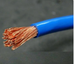
The magnitude of deformation is directly proportional to the complexity of shape, the aspect ratio, and the thickness of the walls, as well as to the rigidity and stability of the material. Therefore, in the design of parts, efforts should be made to minimize the impact of these factors on workpiece deformation.
Especially for large parts, the structure should be rational. Before machining, strict control over the hardness of the blank and defects such as porosity is necessary to ensure the quality of the blank and reduce the deformation it may cause.
Deformation Caused by Workpiece Clamping
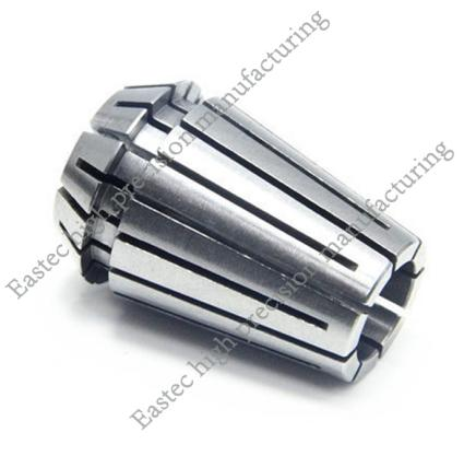
When clamping the workpiece, the correct clamping points must be selected first, and then the appropriate clamping force should be chosen based on the location of the clamping points. Therefore, it is important to make the clamping points and support points consistent, so that the clamping force acts on the support. The clamping points should be as close to the machining surface as possible, and positions where the force is less likely to cause clamping deformation should be chosen. When there are clamping forces in several directions on the workpiece, consider the sequence of the clamping forces. The clamping force that makes the workpiece contact the support should act first and should not be too strong. The main clamping force that balances the cutting force should act last. Additionally, increasing the contact area between the workpiece and the fixture or using axial clamping force can help. Increasing the rigidity of the part is an effective way to solve the problem of clamping deformation. However, due to the shape and structural characteristics of thin-walled parts, they have lower rigidity. Under the action of clamping force, deformation can occur. Increasing the contact area between the workpiece and the fixture can effectively reduce the deformation during clamping. For example, when milling thin-walled parts, elastic pressure plates are used extensively to increase the contact area of the parts subjected to force. When turning the inner and outer diameters of thin-walled sleeves, whether using a simple open transition ring or an elastic mandrel and full arc collets, the method employed is to increase the contact area during workpiece clamping. This method is beneficial for bearing the clamping force and thus avoids part deformation. Axial clamping force is also widely used in production. Designing and making special fixtures can make the clamping force act on the end face, solving the problem of workpiece bending deformation due to thin walls and poor rigidity.
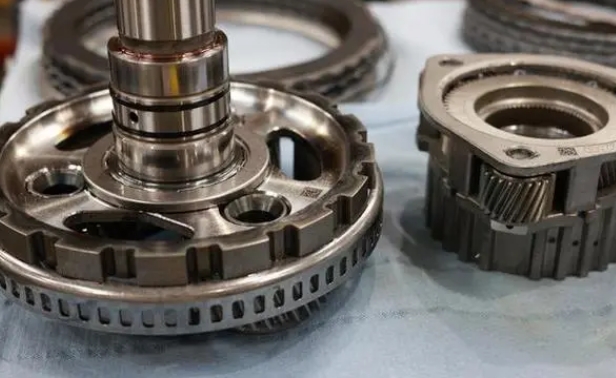
Deformation Caused by Machining
During the cutting process, the workpiece undergoes elastic deformation in the direction of the cutting force, which is commonly referred to as the "cutting phenomenon." To address such deformation, corresponding measures must be taken on the cutting tool. For finish machining, the tool should be sharp to reduce the resistance caused by friction between the tool and the workpiece and to improve the tool's heat dissipation capacity when cutting the workpiece, thereby reducing the residual internal stress in the workpiece. For example, when milling large planes of thin-walled parts, a single-edge milling method is used with a larger main cutting edge angle and a larger rake angle to reduce cutting resistance. This type of tool cuts lightly and reduces the deformation of thin-walled parts, making it widely used in production. In the turning of thin-walled parts, the proper tool angles are crucial for the cutting force during turning, the thermal deformation produced, and the surface quality of the workpiece. The size of the tool's rake angle determines the cutting deformation and the sharpness of the tool's rake angle. A larger rake angle reduces cutting deformation and friction, but if the rake angle is too large, it will reduce the tool's wedge angle, weaken the tool's strength, impair the tool's heat dissipation, and accelerate wear. Therefore, when turning thin-walled parts made of steel materials, a high-speed tool with a rake angle of 6° to 30° is used; for cemented carbide tools, the rake angle is 5° to 20°. A larger tool relief angle results in less friction and correspondingly less cutting force, but if the relief angle is too large, it will also weaken the tool's strength. When turning thin-walled parts, a high-speed steel tool with a relief angle of 6° to 12° is used, and for cemented carbide tools, the relief angle is 4° to 12°, with a larger relief angle for finish turning and a smaller one for rough turning. A larger main cutting edge angle is taken when turning the inner and outer diameters of thin-walled parts. Correctly selecting the tool is a necessary condition for addressing workpiece deformation. The heat generated by the friction between the tool and the workpiece during machining can also cause work


 Customer service 1
  Customer service 2