
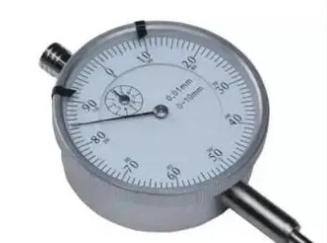
The dial indicator is a universal length measuring tool made using a precision rack and pinion mechanism. It typically consists of a probe, measuring rod, shock-absorbing spring, rack, pinion, hairspring, dial face, and pointer, among other components. How do you use a dial indicator? Watch the video below to find out, and the "gold fans" will understand.
The dial indicator was invented by B.C. Ames in the United States in 1890. It is commonly used for measuring shape and position errors, as well as small displacements in length. The dial face of the indicator is marked with 100 equal divisions, meaning each division corresponds to a movement of the measuring rod by 0.01mm. If the dial face is marked with 1000 equal divisions, then each division represents 0.001mm, and such a measuring tool is called a micrometer.
By changing the shape of the probe and fitting it with the corresponding bracket, variations of the dial indicator can be made, such as thickness indicators, depth indicators, and inside diameter indicators. If a lever is used instead of a rack, lever-type dial indicators and micrometers can be made, which have a smaller range of values but higher sensitivity.
Additionally, their probes can be rotated within a certain angle, adapting to measurements in different directions, with a compact structure. They are suitable for measuring shape and position errors of external circles, small holes, and grooves that are difficult to measure with a standard dial indicator.
Working Principle
The working principle of the dial indicator is to convert the minute linear movement of the measuring rod caused by the dimension being measured into the rotation of the pointer on the scale dial through gear transmission, thus reading the size of the measured dimension. The dial indicator is a measuring instrument that uses rack and pinion or lever and gear transmission to convert the linear displacement of the measuring rod into the angular displacement of the pointer.
Measurement Range
The structure of the dial indicator is relatively simple, with a gear train as the transmission mechanism. It has a small external size, is lightweight, has a low inertia transmission mechanism, and a high transmission ratio. It can use circular scale markings and has a large measurement range, allowing for both comparative and absolute measurements.
Main Uses
It is mainly used for measuring the dimensions, shapes, and position errors of workpieces. The graduation value is 0.01mm, and the measurement ranges are 0-3mm, 0-5mm, and 0-10mm.
Construction and Composition
The dial indicator is mainly composed of three parts: the body, the transmission system, and the reading device.


 Customer service 1
  Customer service 2