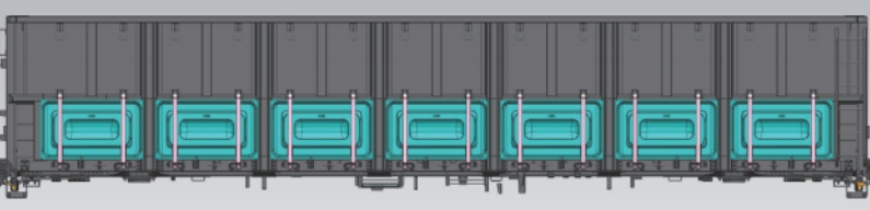
The new - structure C70E general - purpose gondola car is composed of parts such as the center sill, underframe, car body, and side wall. The axle load of the car is 23t, the load capacity is 70t, the length of the car reaches 13,976mm, and the maximum width is 3,180mm. It features significant technological upgrades. The structure of the side - wall assembly has changed. The side - opening doors are cancelled, and seven upward - folding lower side doors are installed at the lower part of each side, forming an embedded labyrinth sealing structure. Meanwhile, the side beams are equipped with self - locking new - type buckles and anti - opening devices. The structure and positioning dimensions of each beam of the underframe have changed, and the center of the side post is aligned with the center of the cross - beam. However, the riveting positions of the side posts and the spacing between high and low holes have been reduced, and fillet welds are used between the fittings. As a result, the assembly accuracy of the underframe and side wall has become a key factor affecting the overall quality of the car.
I. Structural Analysis and Manufacturing Processes of Each Part
1. Center Sill Assembly
(1) Structural Analysis
The center sill is formed by welding a single - piece I - shaped steel, center - sill partitions, front and rear follower - plate seats, and upper center - plate seats, presenting a “几” - shaped structure. It serves as the positioning reference for other parts of the car - body steel structure. Key positioning accuracy dimensions need to be strictly controlled. For example, the spacing between the upper center plates should be controlled within (9210±7)mm, the spacing between the front and rear follower - plate seats is 625mm, and the center - to - center spacing of the cross - beam partition assembly is (1780±2)mm. These dimensions directly affect the assembly of subsequent components.
(2) Manufacturing Processes and Control Measures
During the manufacturing of the center sill, first, comprehensively consider the influence of deflection. Position and assemble the upper center - plate spacing according to 9210mm, and use a scribing rod to accurately mark the positions of each fitting. Before submerged - arc welding of the longitudinal seam inside the center sill, pre - set a deflection of 70 - 100mm to control welding deformation. When assembling the rear follower - plate seat, ensure that the working surface is longitudinally perpendicular to the center sill to ensure uniform stress during the vehicle's operation. At the same time, strictly control the longitudinal center - to - center spacing between two adjacent cross - beam cover - plate assemblies to be (1780±2)mm, and the total length of the center sill to be 12,998mm. Control the dimensions as required during cutting to provide a good reference for subsequent assembly.
2. Bolster Assembly
(3) Structural Analysis
The bolster is composed of upper and lower covers, webs, and partitions, with support plates and stiffeners added on both sides. The upper cover, support plates, and stiffeners are installed during the underframe assembly. Affected by the positions of the upper side - bearings and the side - post rivets at the bolster, the perpendicularity of the bolster web, the bending angle of the lower cover, and its matching with the web are the key points for manufacturing control.
(4) Manufacturing Processes and Control Measures
Use a special assembly device to assemble the bolster. Check the bending dimensions of the lower cover through its profiling. During assembly, make each part closely contact the positioning blocks to ensure the assembly clearance. After assembly, detect the spacing between the two webs, the relevant dimensions between the lower cover and the web, and the perpendicularity of the web. After confirmation, add process supports and perform positioning welding. Use a welding manipulator to symmetrically weld the outer seams between the web and the lower cover to reduce welding deformation and improve manufacturing accuracy.
3. Underframe Assembly
(5) Structural Analysis
The underframe of the new - structure C70E general - purpose gondola car is composed of the center sill, side beams, bolster, end beams, middle longitudinal beams, and small cross - beams. The positioning dimensions and the structure of some fittings of the underframe have changed. To ensure manufacturing quality, adjust and detect the positioning blocks of the underframe assembly jig, and focus on measuring the flatness of the two center - plate bearing surfaces and the height difference between the center - plate bearing surface and the bolster support surface. Meanwhile, the spacing between the fittings at the riveting parts is small and welding is required, which is prone to interference. Controlling the positioning - dimension accuracy of fittings such as the bolster and cross - beams is crucial. The positioning accuracy of the bolster and the unevenness of the four beams also affect the assembly of the car body.
(6) Manufacturing Processes and Control Measures
During the underframe assembly, use the transverse center of the center sill as the reference to assemble the cross - beams, bolster, small cross - beams, and side beams in sequence, ensuring that each beam closely contacts the positioning blocks. When positioning the bolster cross - beam, control the deviation of the two webs from the center to be ≤2mm, and the longitudinal center deviation of the side beam from the center sill to be ≤2mm. Install the two middle stiffeners before assembling the side beam, and detect the distance between the foot - pedal hole and the beam end during side - beam cutting. When assembling the bolster, ensure that the upper edge of the web is 8mm from the upper plane of the middle and side beams, the longitudinal center is 4,605mm from the car - body center, and control the unevenness of the four beams to be ≤6mm. The small cross - beam is 5,285mm from the underframe center longitudinally. The cross - beams are symmetrically distributed along the underframe center, and the spacing between adjacent cross - beams is strictly controlled to be (1780±2)mm. When assembling the end beam, make it closely contact the upper flange of the center sill to prevent welding deformation.
4. Side - Wall Assembly
(7) Structural Analysis
The side wall is composed of side posts, columns, upper door frames, lower - side - door hinge seats, etc. With the new structure, to ensure manufacturing quality and match the deflection with the underframe, adjust and detect the positioning blocks of the side - wall assembly jig, and pre - set a deflection of +3mm in advance. The side wall is the exterior surface of the car body. The quality and aesthetics of the welds affect the overall image of the car. The assembly accuracy of the lower - side - door hinge seats affects the opening and closing of the lower side doors and potential interference. The center of the side post is aligned with the center of the underframe cross - beam. The spacing between the rivet holes is small, and positioning deviation or large fillet welds may lead to unsuccessful riveting. For the embedded labyrinth sealing structure between the lower side door and the door frame, the spacing between the door frames and the staggering amount need to be controlled.
(8) Manufacturing Processes and Control Measures
During side - wall assembly, grind the paint on the side of the side - post cap brim and the lower surface of the cap brim within 5 - 10mm from the edge, and on both sides of the right - angled edge of the upper side beam within 5 - 10mm, to ensure the quality of automatic welding and reduce welding defects such as porosity. Optimize the column dimensions to ensure the staggering amount and assembly clearance between the column and the upper door frame meet the requirements. Pre - set a deflection of +3mm for the side - wall assembly jig, and detect that the diagonal difference of the side wall is ≤6mm. Use the lower side surface as the reference for side - plate splicing to ensure straightness, and position the upper door frame with the lower edge of the side plate as the reference. Position the side posts with their centers, and make a special scribing tool to ensure the spacing between side posts is 1,780mm. Align the positioning of the lower - side - door hinge seats with the reference of the side - beam buckle seats. Analyze the dimension chain of the door frames, optimize and control the manufacturing tolerances to ensure the assembly quality of the door opening. Adjust the corner - post plates for side - wall assembly, and control the assembly clearance with the upper side beam to reserve adjustment space.
5. End - Wall Assembly
(9) Structural Analysis
The end wall is composed of corner posts, upper end edges, end plates, cross - bands, and binding seats. The corner - post plates are assembled on the side walls. Due to a large amount of welding, the whole tends to lean towards the inside of the side wall. The width of the end wall needs to match the width of the underframe, so the overall width of the end wall needs to be controlled.
(10) Manufacturing Processes and Control Measures
Assemble three cross - bands between the two corner posts. Control the overall width of the end wall by controlling the overall length of the cross - bands. Cut the cross - bands to a length of 2,700mm. The perpendicularity of the cutting surface during sawing is required to be ≤2mm. In this way, the overall width of the end wall can be controlled at 2,900mm, making the corner - post plates closely fit the corner posts, improving the welding quality and the car - body assembly efficiency.
6. Car - Body Assembly
(11) Structural Analysis
The car body is composed of the underframe, side walls, end walls, lower side doors, and hand - brake fittings. For the embedded labyrinth sealing structure between the lower side door and the door frame, the height dimension of the door opening needs to be strictly controlled. The longitudinal center deviation between the side wall and the underframe needs to be focused on. The side wall has few connection parts and welding parts with the underframe, so stable and safe assembly needs to be ensured. At the same time, the lateral bending of the upper side beam of the side wall, the inner width of the car body, and the inclination of the car body need to be controlled.
(12) Manufacturing Processes and Control Measures
Use the center of the underframe and the center of the side beam as the references for side - wall assembly, consistent with the positioning references of other fittings. Adjust the side posts on both sides of the middle lower - side - door opening to ensure that the longitudinal center deviation of the side wall from the longitudinal center line of the side beam is ≤1mm. Adjust the height of the side wall with the upper flange of the side beam as the reference to ensure the door - opening height is 807mm. During side - wall assembly, clamp the upper side beam at the top and support it at the bolster columns. Adjust the dimensions from the middle to both sides, then press the side posts tightly and weld the seams between the backing plate and the side - post flanges. To ensure the inner width of the car body and the lateral bending of the upper side beam, make the side wall expand outward by 15 - 25mm on one side, assemble the inner reinforcement seats of the side posts, and perform positioning welding. Check that the perpendicularity of the corner posts to the horizontal plane is ≤8mm during end - wall assembly.
7. Side - Post Drilling
(13) Side - Post Riveting Analysis
In the riveting structure, the diameter of the rivet hole needs to match the diameter of the blind rivet. An oversized hole diameter affects the riveting quality. The distance between the side - post rivet holes and adjacent fittings is small, and there are manufacturing tolerances in the assembly of the bolster cross - beam and side wall. To ensure non - interference during riveting and qualified riveting quality, the drilling accuracy of the side posts needs to be strictly controlled.
(14) Manufacturing Processes and Control Measures
Before drilling the side posts, use a clamping device to clamp the car body to ensure stable operation. According to the process requirements, the deviation of the holes on both sides from the center of the side post should be ≤2mm. Use a scribing tool to mark the positions of the two holes on each side of the side post. After positioning the combined drill, check the alignment of the drill bit to ensure that the center deviation of the holes on both sides meets the requirements and improve the riveting quality.
This article conducts an in - depth analysis of the structure of each part of the new - structure C70E general - purpose gondola car and formulates a reasonable process plan. Through the implementation of various technical measures, the key dimensions of the underframe and car body are effectively controlled, and the positioning accuracy of related dimensions is stable and reliable. This plan has been fully verified in mass production. The method is practical, and the measures are effective, providing valuable experience for the subsequent production of similar products.


 Customer service 1
  Customer service 2